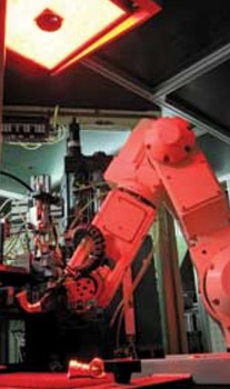
RoboVis enables complex plumbing parts to be automatically assembled
Integrating machine vision with a six axis robot has allowed complex plumbing parts to be automatically assembled.
As a business partner to some of the world’s best-known plumbing and heating suppliers, the Pegler Yorkshire Group offers numerous types of pipe fittings in different sizes and configurations. When manufacturing copper and brass elbow joints, tees, and valves, various components must be assembled before the finished item can be shipped to the customer.
Because of the wide range of parts and relatively small batch sizes Pegler Yorkshire needed to design and build highly flexible assembly systems that could accommodate a wide range of parts, limited only to the size (for instance 15mm or 22mm). To feed component bodies parts into these machines Pegler Yorkshire chose Kawasaki Robot UK to provide robots and FS Systems to provide vision systems to automate this task.
Parts are fed from either bowl or hopper feeders onto 200mm wide conveyor belts running at 5m/min from where the component bodies are presented to the robot for pick’n’place into a fixture in the machine. FS Systems’ RoboVis systems are used to take an image of the conveyor and pass component co-ordinates to the robot for picking, having first ascertained the part nearest the end of the conveyor that can be picked without the robot colliding with an adjacent part. When the conveyor sensor detects a component the conveyor is stopped, so the component can be picked from a stationary position. This is especially important for cylindrical parts that may roll. Suitable conveyor belting was chosen to limit the rolling of parts and to minimise the reflections of the lighting back to the camera.
As many as 10 different parts can be randomly located across a 260 × 200-mm area of the conveyor. For the robotic system to properly locate each part correctly, illumination plays a vital role. Because brass and copper parts are specular, they are difficult to illuminate. The system must also compensate for metal fragments from the production process that may be present on the conveyor belt.
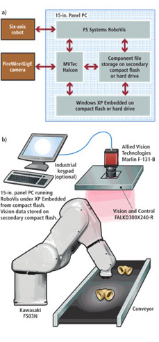
Ringlights are not suitable for such an application because light will reflect differently on a cylindrical part depending upon its location on the belt, making it difficult to obtain an image with good, consistency across the viewed area.” Instead, FS Systems contracted Vision & Control to build custom 300 × 240-mm, 630-nm (red) LED panels (FALKD300x240-R) that are placed approximately 1 m above the conveyor. By placing a camera in the centre of this panel, reflected direct-on-axis illumination could be captured by a Marlin F-131B FireWire camera from Allied Vision Technologies (later systems use Basler Scout GigE cameras). Images from the camera are then transferred to a host PC, which is interfaced to the robot controller of a six-axis robot from Kawasaki Robotics over an Ethernet interface. Before picking any specific part from the conveyor, the system must determine which part can be selected most efficiently. After this is determined, the system checks whether there will be any potential collisions with any other parts on the conveyor. If there is no such conflict, then the part is picked; otherwise, the robot must pick another part from the conveyor. In the event that no parts can be picked, the conveyor is advanced and all the parts are recycled back to the hopper for re-presentation.
In the RoboVis systems installed at Pegler Yorkshire Group approximately 95% of the parts presented can be picked, leaving only 5% to be recycled through the system. Determining which parts can be picked in this manner is achieved by analysing the images captured by the camera. As a Certified Integration Partner for MVTec Software, FS Systems uses Halcon running on the host PC to perform the analysis which is embedded into the RoboVis software.
Part recognition
Before parts can be processed, the system must be calibrated. A known good part is placed on the conveyor belt by the robot at a known position and an image is captured. Any metal fragments within the image are removed by smoothing the image. To identify the position of part, the image is then thresholded to segment the pipe fitting.
After segmentation, a geometric shape-recognition function is used to create a mathematical model of the part. The position of the part at this point is known as the datum position. In operation, the system captures images of multiple pipe fittings within the camera’s field of view. Once again, smoothing, thresholding, and geometric shape-recognition algorithms are applied to determine pick co-ordinates, relative to the datum position for the robot.
RoboVis has been designed to be easy to use, either as an operator (choosing which parts to run) or as a machine setter (creating new component recipes). It was necessary to develop a user interface that allowed the operator to visualize the system in action, amend high-level image-processing functions, and test the system before it could be placed in production.
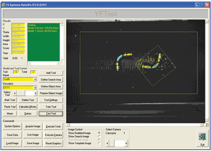
Using the system interface, operators can visualize objects, calibrate the system using a known object area, and select the number and order of image-processing functions.
Objects can be seen as they appear on the conveyor and functions such as thresholding can be highlighted to show the operator which objects the system will pick as well as its coordinates (top left). Using a Model and Tool Control, the operator can also calibrate the system using a known object area and select the number and order of image-processing functions that the system will run. More than 15 RoboVis systems are now in use at Pegler Yorkshire alone in the UK, USA, and Hungary.