
Laser Drill Visual Inspection Systems
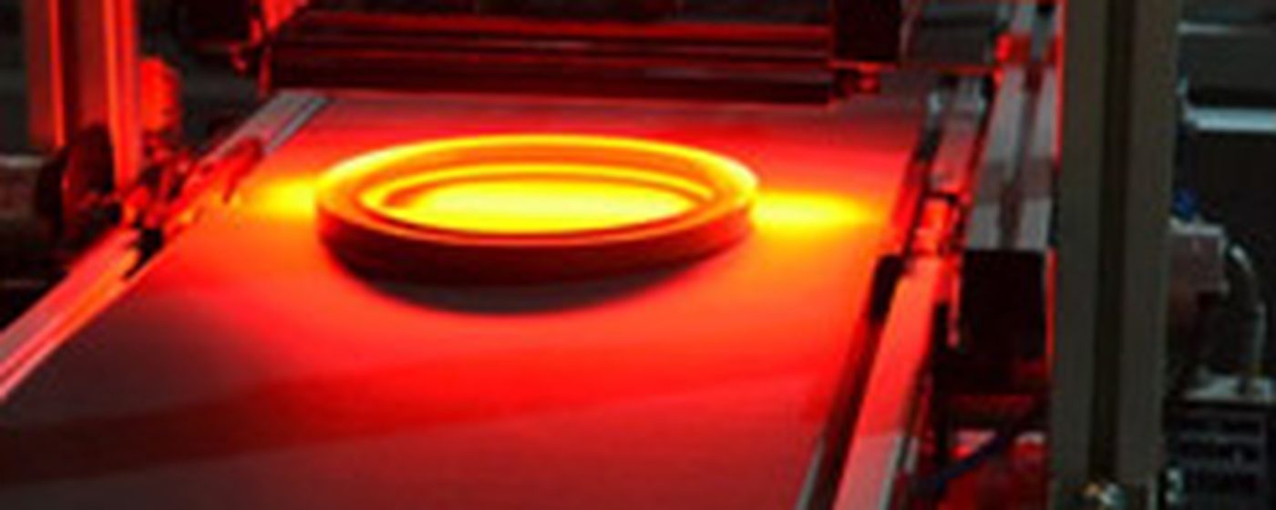
Our customer, RNA Automation, was contracted to design and manufacture an automated laser drilling process cell and inspection system for a range of plastic moulded components. The hole diameters to be drilled ranged from 15µm to 50µm.
The system incorporated a bowl feeder, vision guided robot, walking beam transfer system, laser drilling system, vision inspection stations and a control system. The project was for a global leader of gas detector manufacture for the mining industry.
Challenge
Provide a flexible automation solution for various different components (11 variants); provide quick and easy changeover between component runs; and provide 100% inspection on position, entry hole size and exit hole size.
Solution
This particular configuration utilises one laser drilling station and three camera stations to verify part accuracy. To begin the process, the components are presented to a vision guided Kawasaki robot by an RNA bowl feeder that feeds parts onto a pick conveyor mounted below the robot. The robot then picks the component and places it in the correct orientation to a nest mounted on a walking beam transfer system.
With the walking beam transfer system, the component is lifted up by a gripper and moved one position ahead to the laser station. The laser drilling process is triggered and drills the correct size hole in the desired position. The laser drilling system is supplied by ES Technology, who have extensive experience in laser drilling, welding & marking systems, delivering quality performance at high speed and with great precision. After the component is drilled, it is lifted up again and moved to the next station for the first inspection.
RNA enlisted the expertise of their machine vision partner Fisher Smith, who are leading experts in the field of machine vision and industrial control systems. The vision system incorporates three camera stations, with the ability to inspect each component for position of the hole, entry hole size and exit hole size. Components that fail the vision inspection are rejected into a reject bin; "good" components are fed into a collection bin for a bagging system, and a separate bin for random sampling (1/1000 of "good" components for further off-line checking).
The application presented Fisher Smith with numerous technical challenges, particularly in relation to the measurement of the drilled hole size. Due to the functionality of the device, both the size of the hole at entry and exit are measured. Two four-megapixel cameras using Vision & Control magnifying telecentric lenses are utilised; however the depth of field of the lens (0.005mm) for such a small field of view (1.2mm) is far less than the variation in material thickness. To overcome this, Fisher Smith specified precision servo stages to move the camera/optics and illumination vertically whilst continually acquiring images, then employed a custom algorithm to identify the image where the hole edge is in focus. Further algorithms were developed by Fisher Smith to measure the hole size.
This system has the flexibility to handle various components (11 variants). The bowl feed system utilises an innovative quick-change tooling system that speeds up tooling changes. Each component variant is provided a unique barcode which contains all the parameter set-up for that particular component; when the barcode is scanned, the data is retrieved by the control PLC/HMI and the operator changes the tooling models to meet those parameters. The PLC automatically recognises if incorrect sets of tooling are fitted. This validation process takes just seconds and eliminates the risk of inadvertent human errors — a fully validated changeover to switch from one component to another can be accomplished in less than 5 minutes, resulting in improved uptime and productivity.